To build Tame or Duck modules, you must make the special DIY “vactrols”.
These can be fun to build, because it is an unusual thing to accomplish. But if following the instructions makes you nervous (or worries the voices of mad perfectionism driving many of us!) then lower the stakes: decide that the first DIY “vactrol” you assemble will be to throw away: once you have the hang of making one, making others is quite simple! Remember: all that will happen if the components are not well-chosen is that each section will have different responses and strength: you might decide it is a bug not a feature.
Here are the instructions. You will need:
- Two LEDs per vactrol. The colour is important (see Release Notes)
- A light dependent resistor. These are available from many sources. However, photoresistors have poor consistency (varying up to 50% in response even in the same batch, according to some page) so unless you select them to be consistent, the actual strength of response is unpredictable.
The important thing is to use an LDR with a low on-resistance (resistance with the light on) but not too much: 5k or less, e.g. GL5506 or GL 5516 at a pinch. A GL5528 is probably fine as well. - Three sizes of heatshrink tubing:
- One small suitable for keeping legs apart.
- One as the thorax tube (1 cm wide when squashed flat)
- One as the package tube (1.5 to 1.5 cm wide when squashed flat)
A “vactrol” is a brand name that is now generic for a voltage (or current) controlled resistor made from an LED and a light-dependent resistor (LDR). They were widely used by the 1960s synth designs of Don Buchla. Vactrols go through periods of being quite expensive or difficult to obtain. However, making your own is fairly easy, with the main technical difficuly being making sure that they are packaged so that no external light can get in.
There are several good videos on YouTube giving hints. The main difference is that the Vactrols needed for Tame and Duck are not the standard configurations: official Vactrols are either 1 LED and 1 LDR, or 1 LED and 2 LDRs. However, Duck and Tame need 2 LEDS and 1 LDR.
This is because we feed the LEDs with an audio signal, and we want 1 LED to be driven by the positive parts of the wave cycle, and the other LED to be driven by the negative parts. So our Vatrols just have 4 leads: the two ends of the LDR and an active and 0V lead for the LEDs.
1. Selecting LDRs
It is necessary to select the LDR for good efficiency and consistency. What do you test for? If you want the unducked signal to be as unaffected as possible, you choose LDRs with a high “dark” resistance; if you want maximum ducking, you choose LDRs with a low “on” resistance.
- I tested 90 LDRs from the same bulk purchase, by at night measuring their resistance under a desklamp and sorting them in 2-3k (the best), 3-4k, 4-5k, and 5-6k ohms: I got 10, 30, 35, 14 plus 1 non-functioning. This is a range of 2.2k to 5.2k, which is, in these circuits, 150% difference: way too much for predictability.
- LDRs are a commodity, like resistors, where the price rapidly drops when you buy in bulk: in fact it may be difficult to obtain them in ones and twos. I buy batches of 50 or 100. Even if you only want to buy the minimum, you are well advised to get a few spare, to allow selection.
- Test with an ohm-meter their on-resistance in a medium-light (less bright than sunshine, but brighter than a domestic room light: a bright white desklight at night might be great). I spread them over a desk in very rough order, to form 4 or 5 groups. Select the ones with the lowest or most common on-resistance.
2. Select LED (Optional)
Test your LEDs with a 2.2k resistor and a 9V battery. Check the color. Do not select red as it is usually not visible to the LDRs.
- I use warm white, orange, yellow or green: optimal performance will come from matching the LED spectrum with the LDR response, however in the use of Duck and Tame, we are do not need a brilliant dynamic range.
- Do avoid new generation super-intense LEDs or 1970s old generation: just use generic modern LED.
3. Glue the LEDs
This makes them easy to handle.
Superglue the two LEDs together, flat edge to flat edge. This makes them more manageable. CHECK: The leads will be in a line: long, short, short, long. TIP: Use the PCB to help form and while drying:
- insert them (don’t solder them yet) until about about 50mm of lead under the LED protrudes (less than the size of a mid size LED) then
- bend then 90 degrees out.
Glue the edges and let it dry. (Don’t glue them to the board by mistake!) This is just to keep them together, to make manipulation easier. Avoid getting glue on the very top of the LEDs. In the picture below, you can see the white-ish LEDs on the bottom glued together (but not soldered in.)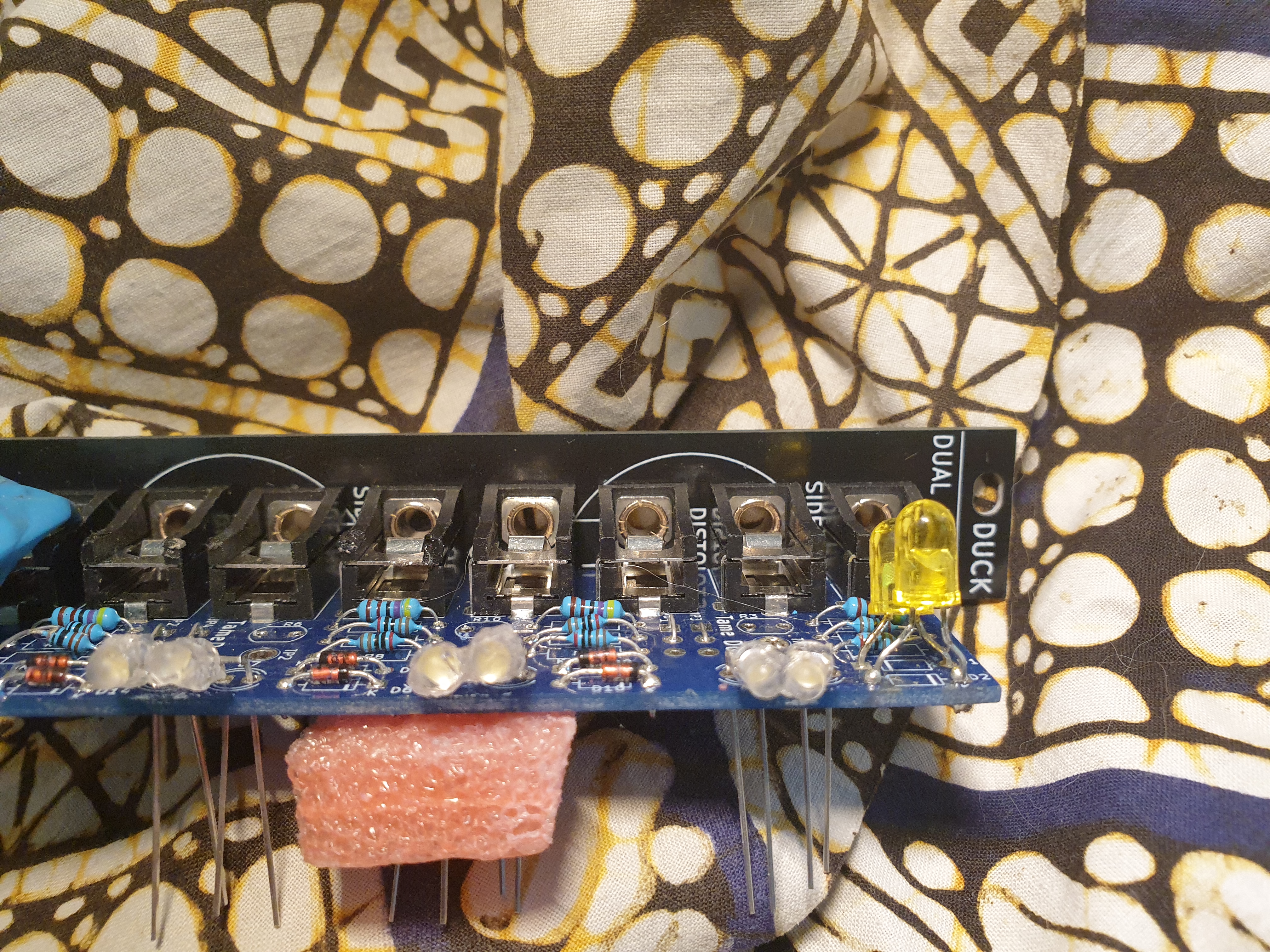
Take them out. (When installing them again, they will be spun around 180 degrees to face inward: you wont need to bend the LEDs again, except to make them snug.)
4. Heatshrink
Put on heat shrink:
Leads: Put on a small 1 cm of smallest heatshrink over each inner leg, just enough to go from the LED and around the bend. Shrink it (use a quick flame or the body — but not the tip!– of a soldering iron).
Thorax: Cut 2cm (1 small inch) of medium heatshrink (black preferred, to block outside light) just enough to cover the LEDs, inset the LDR to abutt the LEDs. Shrink it; don’t allow the heat shrink to melt into between the LDR and LEDs.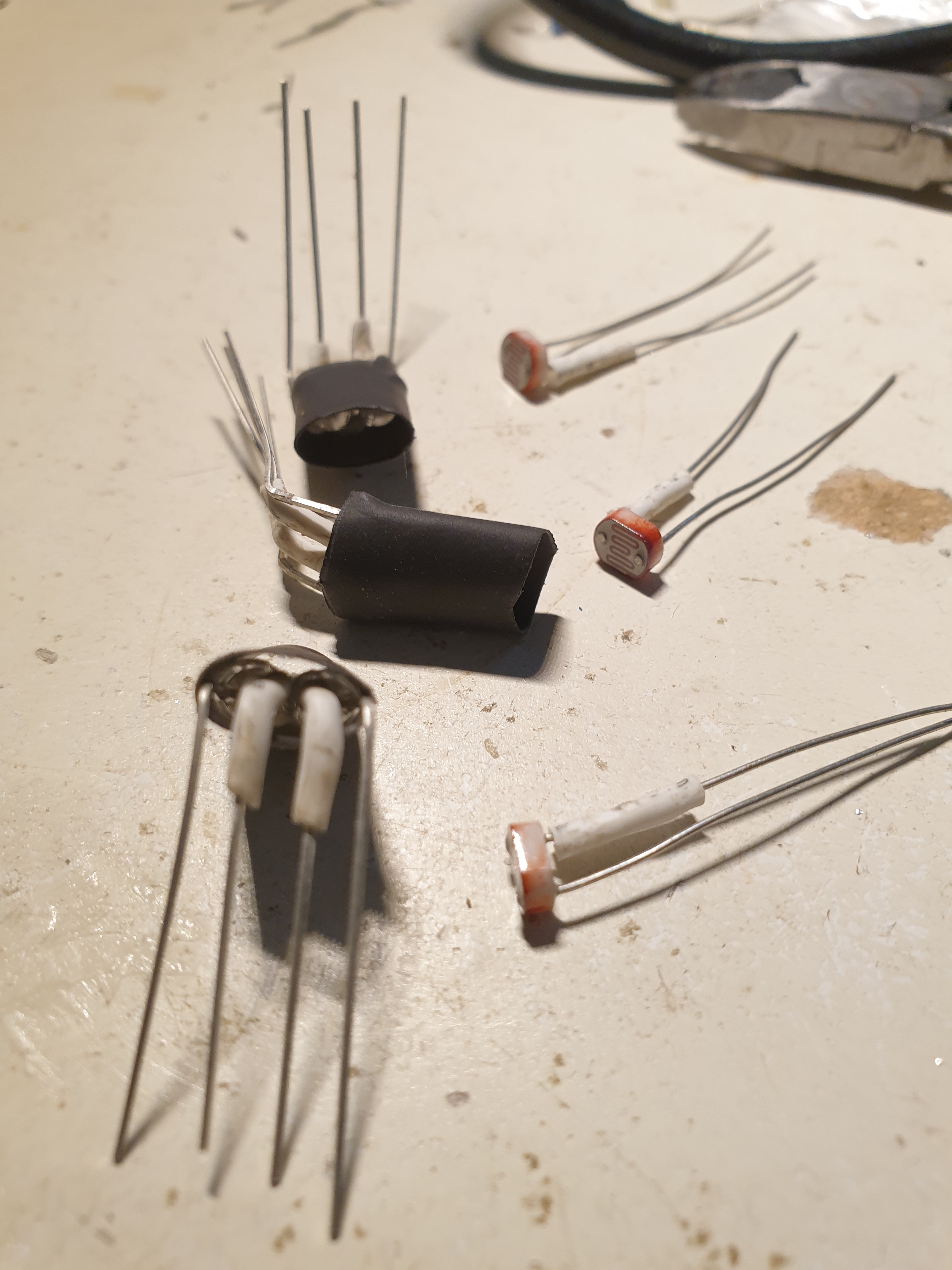
You may care to have little top-flaps on the heat shrink, to provide addition shade.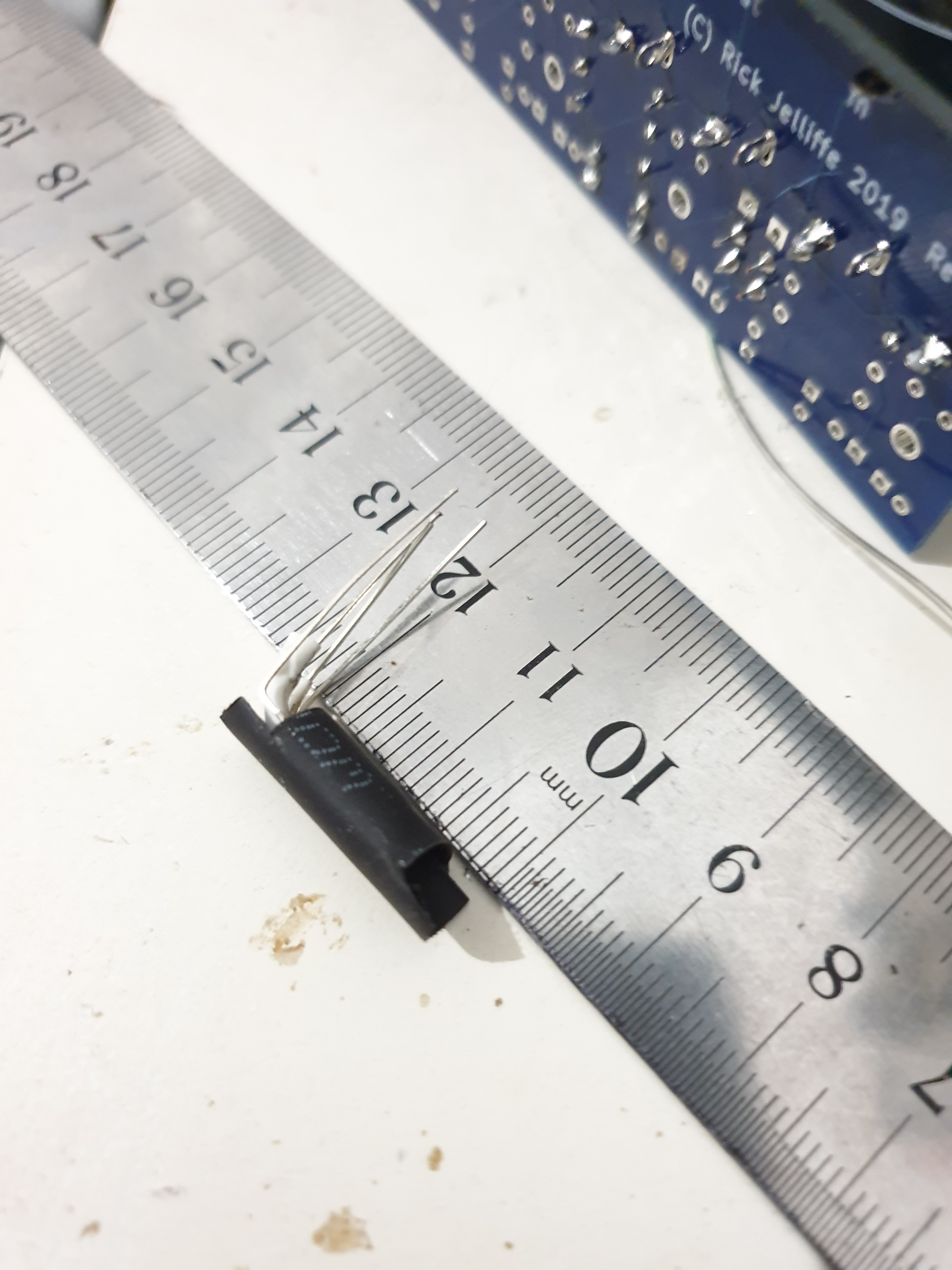
Outer Case: Now put 3-4cm (2 small inches) medium black or blue heat sink to cover the whole thing and protect the LDR leads. Shrink it. (Again, you may like to have addition top-flaps.) Melt the ends together, trying to get as good light-proof seal as possible. (If you prefer the bakable modeling clay method, use that.) 
Bend the LDR leads 180 degrees back (then 90 degrees down) so the home-made Vactrol fits in place overlapping the sockets, but not going outside the silhouette of the panel (which would complicate installation of the Tame module into your rack.) This bending will also block external light even if the seal on that end is not so good.
5. Solder in
Solder in, but not flat against the PCB: keep enough height that you could access under the Vactrol to rap in tape if needed.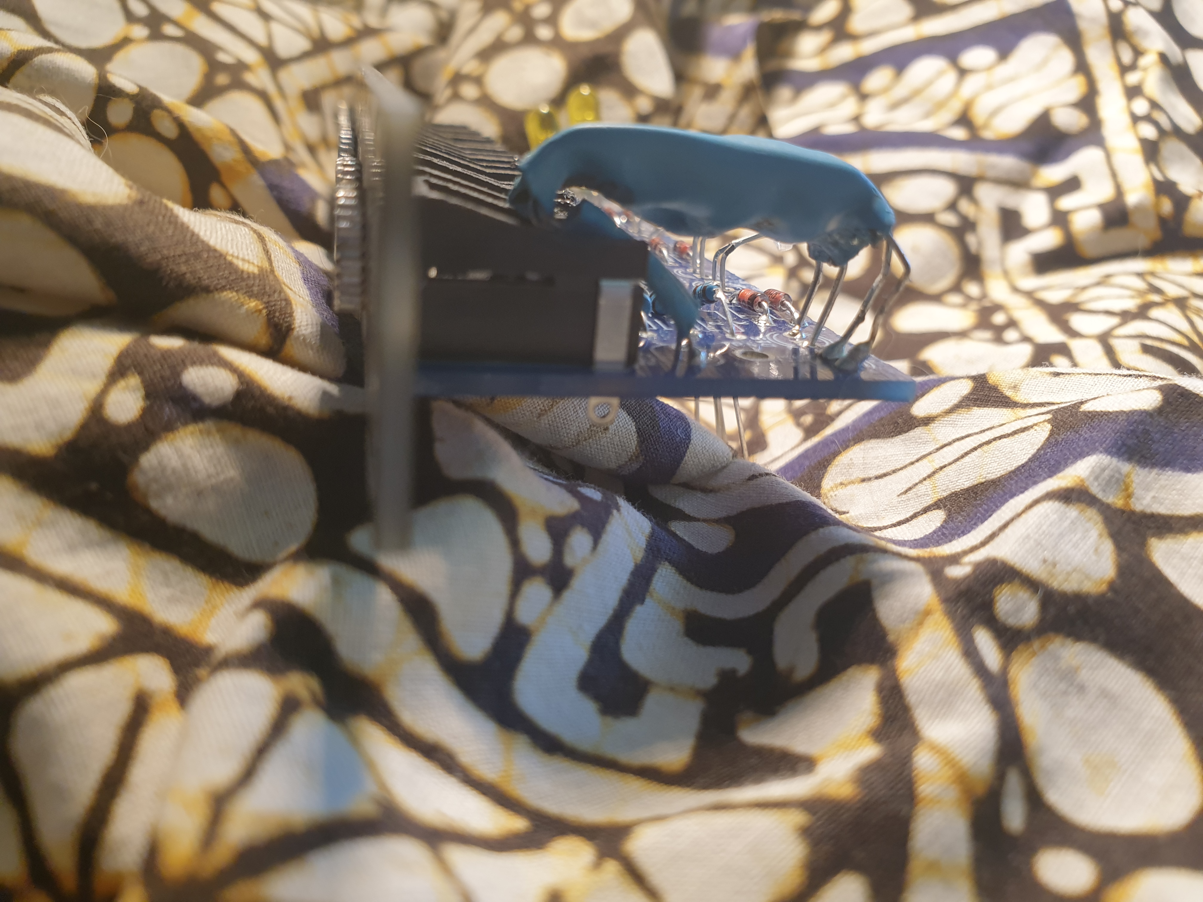
7. Check for Bad Seal
If when testing, if you can see much light coming out, that means some light can go in: this will cause erratic behaviour. Wrap some tape or clay around it, or devise some better method.
(Actually, being able to glimpse a tiny amount of light on one end is quite useful, to re-assure the wild-eyed builder that the LEDs are in fact working, and perhaps not so harmful if the module is going into a relatively dark case.)
8. After
The Duck/Tame boards allow you to put in scaling resistors, to choose how strong the ducking effect will be. If the effect with the resistor value specified in the BOM is not strong enough, solder some resistor (e.g.same value) in parallel on the bottom of the board, to reduce the value.
